
Circuit Design
Circuit concepts, component selection, power supplies, interfaces, and clearly documented schematics.
Precision electronics development — from the initial concept through circuit design and PCB layout to prototype implementation. Engineered down to the details.
From individual engineering challenges to complex electronics projects: a structured approach connects circuit design with its intended application.
Circuit concepts, component selection, power supplies, interfaces, and clearly documented schematics.
Component placement, multilayer PCB design and routing, taking manufacturability, current paths, and signal integrity into account.
Manufacturing preparation and support with assembly, commissioning, and initial functional tests, as agreed.
Engineering electronics as part of complete systems with motors, sensors, actuators, and mechanical components.
High-quality PCB renders, assembly models, and clear visualizations for technical coordination.
Preparation of schematics, bills of materials, Gerber and drill files, and other agreed project documentation.
From simple two-layer designs to more complex four- and six-layer PCBs, tailored to the project requirements.
Discuss a PCB ProjectL1 · Top Copper · Signals and component connections
Selected engineering and CAD showcases focusing on PCB architecture, system integration, and detailed design.
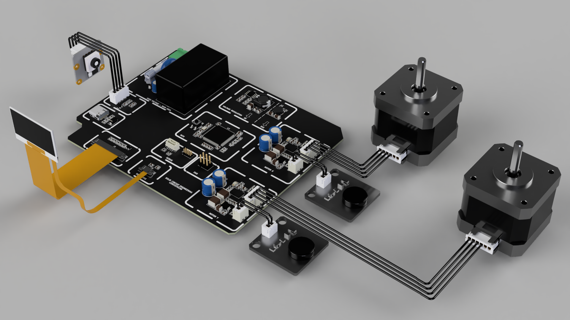
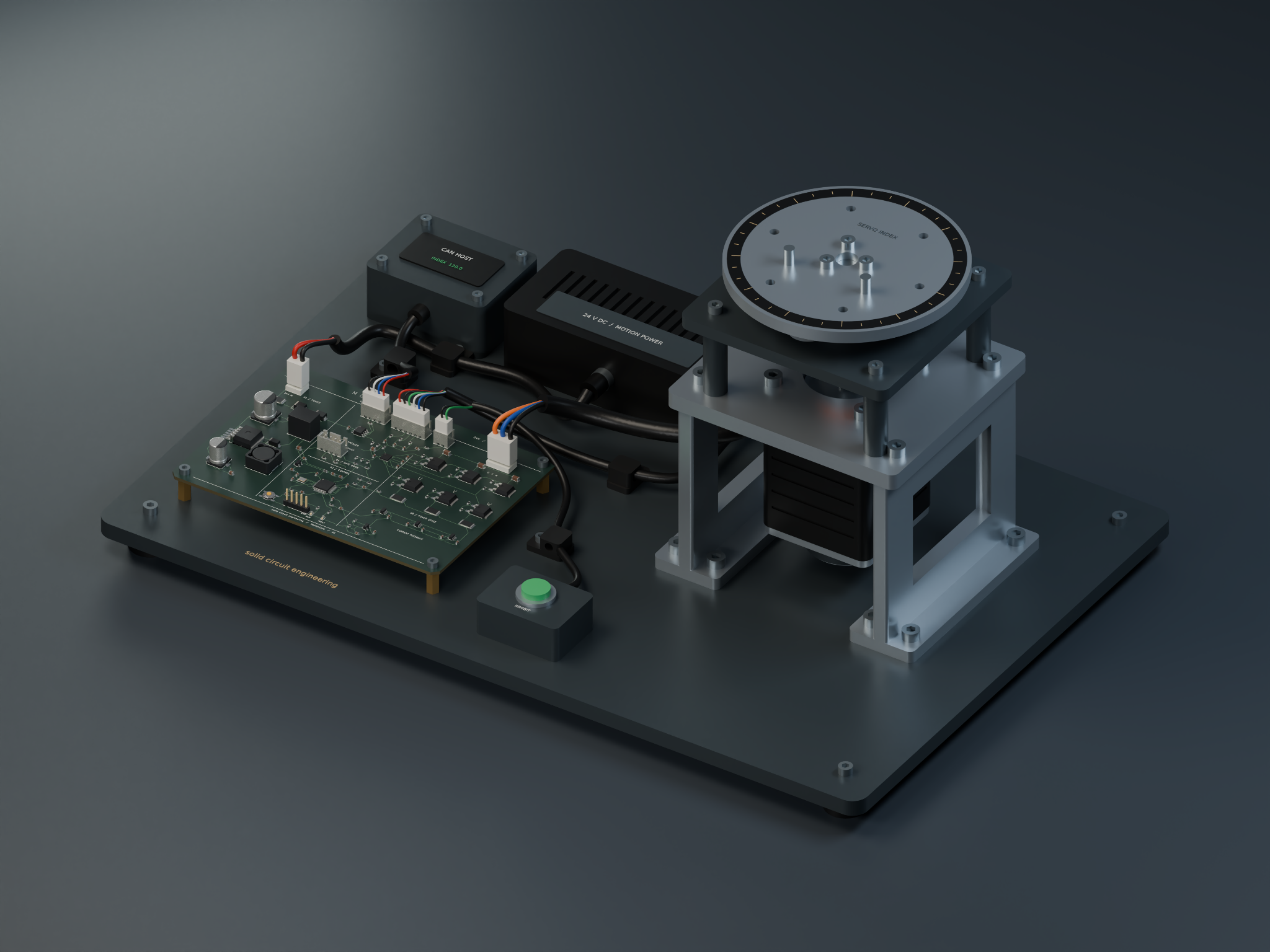
Engineering visualization of a controller PCB with two motor drives, external modules, and a display connection — from PCB concept to complete assembly.
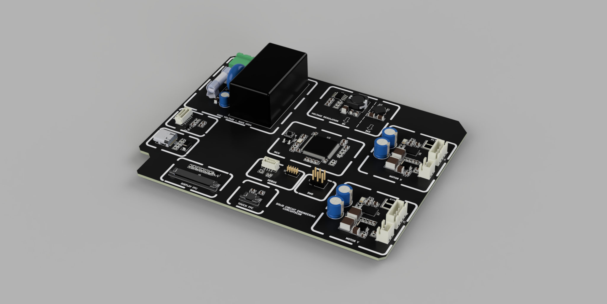
Detailed PCB visualization featuring separated functional sections, interfaces, and motor driver stages.
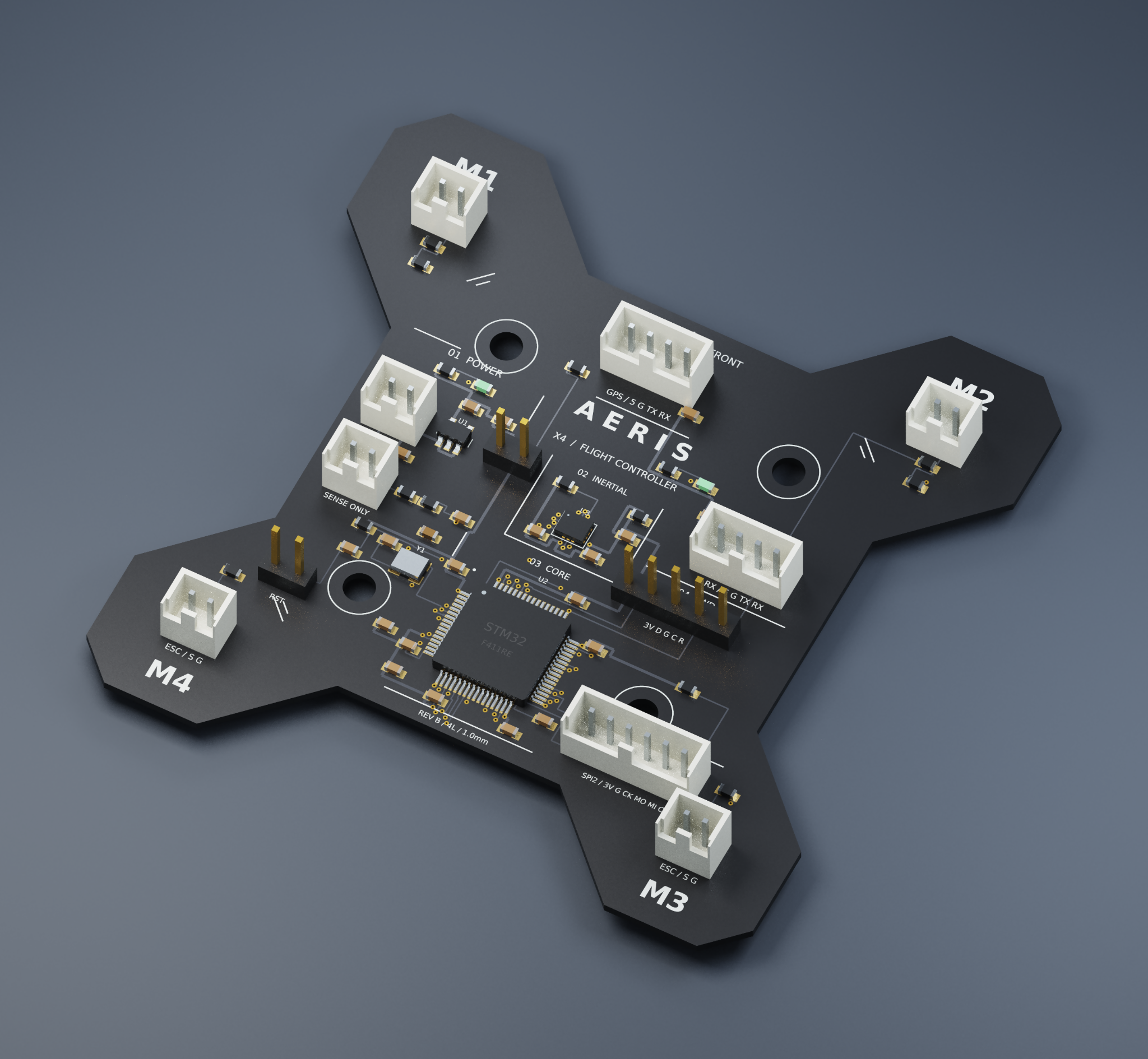
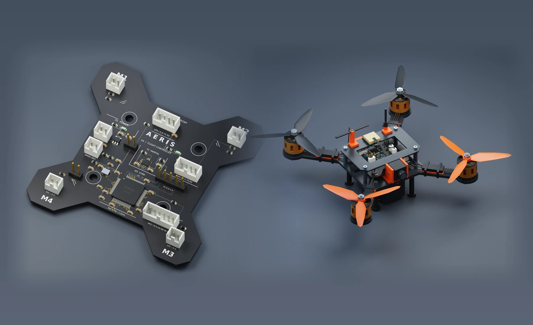
Electronics concept with a central processor, sensor and motor connections, and a compact form factor.
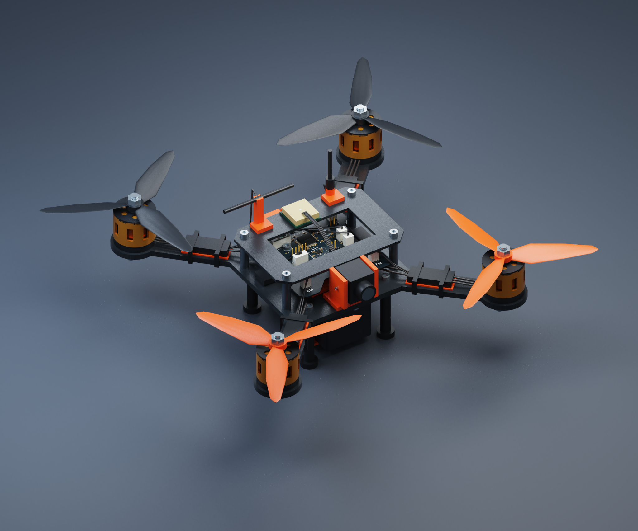
Showing how the flight controller, frame, drive components, and wiring work together as a complete system.
Note: The projects shown are engineering and visualization showcases. Images do not constitute evidence of series production, certification, or completed product validation.
Interactive views of component functions and typical interfaces, using our own CAD renders and explanatory diagrams.
Explore selected functional areas of our MotionCore PCB rendering up close.
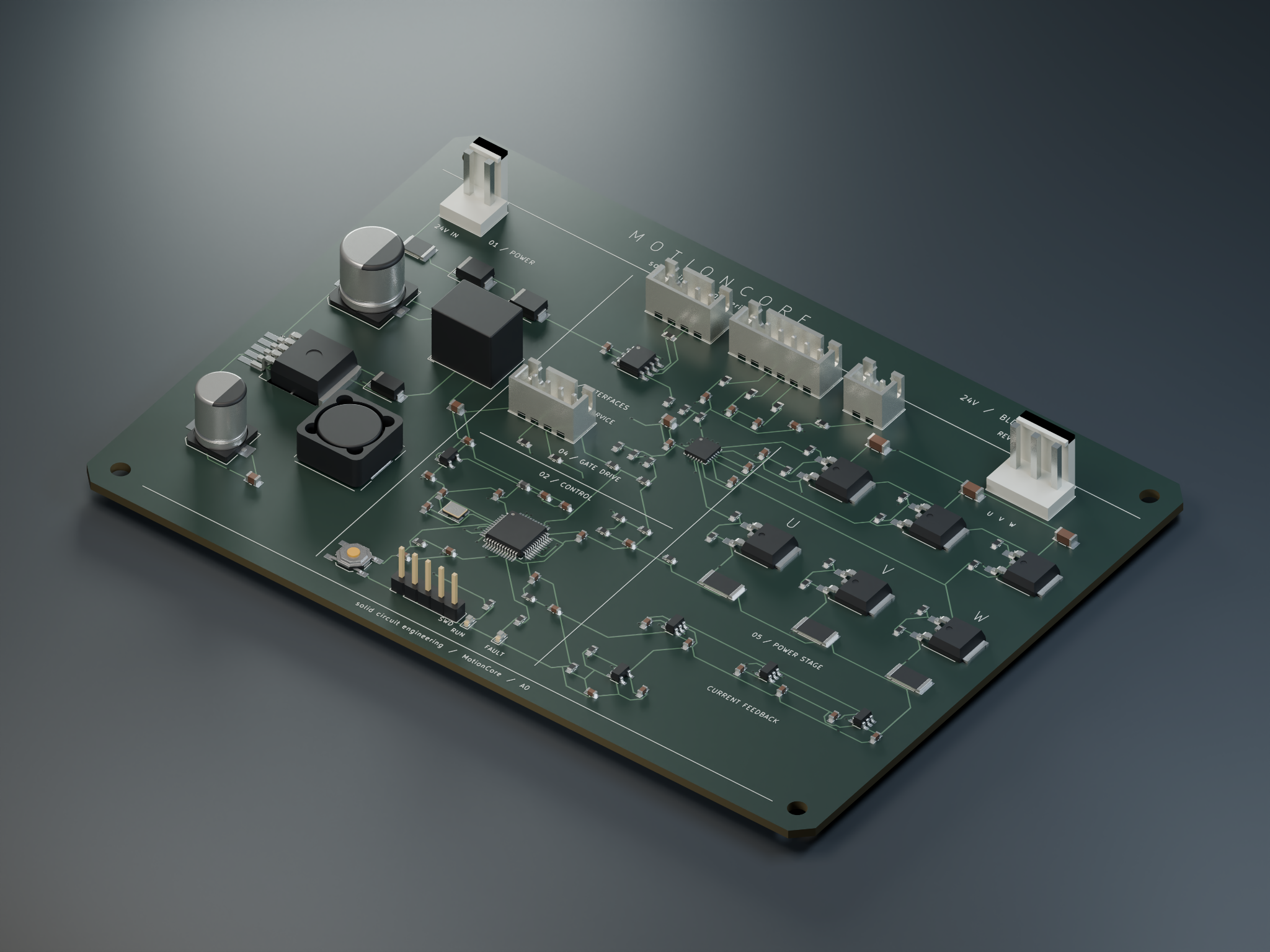 Select an area to explore.
Descriptions refer to visible functional areas of the board and are not complete component specifications.
Explore typical communication and control interfaces in an embedded system.
Robust differential communication between controllers, often used in industrial and mechatronic systems.
Conceptual diagram of typical interfaces; it does not claim to represent the exact pinout or features of the showcased MotionCore or flight controller projects.
Every project is different. Our process provides a clear structure — from the first inquiry through engineering decisions to the agreed handover.
Select a step to explore that stage of development.
Clarify goals, scope, functions, and requirements.
Define the architecture, components, and technical approach.
Develop circuits, protection functions, and connections.
Place, route, and design for manufacturability.
Coordinate PCB ordering and manufacturing.
Assembly, commissioning, and agreed testing.
Hand over the prototype and engineering documentation.
Review results, resolve open questions, and agree on next steps.
Scope, acceptance criteria, and deliverables are agreed for each project. Steps may be omitted or added based on the assignment.
The goal is more than an attractive PCB model: depending on the contract, the result is a verifiable engineering milestone backed by technical documentation.
Clear technical deliverables support manufacturing, future development, and later revisions.
Documented circuits and defined interfaces.
Gerber, drill, and optional assembly files.
Structured component list for sourcing and assembly.
CAD files and project-specific handover documentation.
Solid Circuit Engineering combines electronics development with expertise in mechatronics. Our technical foundation includes a master craftsman qualification in mechatronics, electrical machine engineering, and automation.
We focus on carefully engineered circuits, clean PCB layouts, and real-world applications — from motor controllers and sensors to compact embedded systems.
Answers to common questions before starting a project.
Yes. Individual services such as schematic design, PCB layout, or documentation can be commissioned independently.
No. An initial idea, existing documentation, or a functional description is often enough for the first discussion. Open requirements can be clarified during the concept phase.
This depends on the agreed scope. Typical deliverables include schematics, PCB manufacturing files, bills of materials, 3D files, and technical documentation.
Support with manufacturing, assembly, and commissioning may be available depending on the project and equipment. The scope is agreed in advance.
Start with a short description of the application, desired functionality, and known technical constraints. We then discuss the scope and next steps.
Tell us about your project — whether it is new electronics development, PCB layout, or a specific prototype.
Choose email or our structured inquiry form.